Lexus ES330 (2004-2007) Wiring Diagram: Left Kick Panel Focus
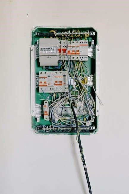
Locating the driver side junction block (J/B) behind the left dash panel is crucial; this area houses vital connections for starting‚ charging‚ and other systems․
The 2004-2007 Lexus ES330 utilizes a complex electrical system‚ demanding precise wiring diagrams for effective troubleshooting and repair․ Understanding the vehicle’s architecture is paramount‚ as numerous components interconnect through a network of wiring harnesses and junction blocks․ Accessing accurate diagrams‚ particularly those focusing on the left kick panel area‚ is essential for diagnosing issues related to the starting‚ charging‚ and accessory systems․
The left kick panel serves as a central hub for several critical electrical connections․ It houses the driver-side junction block (J/B)‚ which distributes power to various circuits․ Identifying the correct wiring diagram version for your specific ES330 model year is crucial‚ as minor variations can exist․ These diagrams detail the color coding‚ wire gauges‚ and connector pin assignments‚ enabling technicians to trace circuits efficiently․ Online resources and repair manuals often provide downloadable PDF versions of these diagrams‚ offering a convenient way to access the information needed for successful repairs․
Understanding the Left Kick Panel Area
The left kick panel within the 2004-2007 Lexus ES330 is a concentrated point for crucial electrical components․ Primarily‚ it houses the driver-side junction block (J/B)‚ a central distribution point for power throughout the vehicle․ Accessing this area requires careful removal of the interior trim panel‚ revealing a complex network of wiring harnesses and connectors․
Within the J/B‚ you’ll find numerous fuses and relays governing systems like the starter‚ charging system‚ and various accessories․ Identifying these components requires referencing a detailed wiring diagram․ The area also contains connections for the body ECU‚ impacting several vehicle functions․ Careful attention to wire colors and connector pin assignments is vital during any diagnostic or repair work․ Understanding the layout and function of this area is key to efficiently resolving electrical issues within the ES330․

Charging System Wiring (2004 ES330)
Essential charging components—alternator‚ battery‚ and related fuses (A107A57Acc‚ Alt-S‚ AltlAm2)—are interconnected‚ with key connections found near the left kick panel․
Charging System Components Overview
The Lexus ES330’s charging system relies on a coordinated effort between several key components to maintain battery charge and power vehicle electrical systems․ The alternator generates AC voltage‚ converted to DC for charging‚ while the battery stores this energy for starting and powering accessories when the engine isn’t running․ Several fuses protect the circuit‚ including the A107A57Acc fuse‚ the Alt-S (5A) fuse‚ and the AltlAm2 (30A) fuse․
Understanding the location of these components and their wiring is vital for troubleshooting charging issues․ The body ECU‚ connected to the driver-side junction block‚ plays a role in monitoring and regulating the charging process․ The charge indicator on the combination meter provides visual feedback on the system’s status․ Tracing the wiring from the alternator‚ through the fuses (often accessible near the left kick panel)‚ to the battery and ECU‚ is essential for diagnosing problems․ Proper ground connections are also critical for efficient charging․
A107A57 Acc Fuse Location & Function
The A107A57 Acc fuse is a crucial element within the 2004-2007 Lexus ES330’s charging system‚ typically found within the driver-side junction block‚ often located behind the left kick panel․ This fuse‚ rated at 120A‚ provides power to various accessories and systems when the ignition is switched on․ Its primary function is to protect these circuits from overcurrent‚ preventing damage to components and potential electrical fires․
A blown A107A57 Acc fuse can manifest as a complete loss of power to multiple accessories‚ or even a no-start condition․ Troubleshooting requires careful inspection of the fuse itself – visually checking for a broken filament; Replacement should always be with a fuse of the identical amperage․ Before replacing‚ it’s vital to identify the cause of the short circuit that blew the fuse‚ as simply replacing it without addressing the underlying issue will likely result in it blowing again․
Alt-S Fuse (5A) – Purpose and Troubleshooting
The Alt-S fuse‚ a 5-amp component in the 2004-2007 Lexus ES330’s charging system‚ plays a vital role in protecting the alternator’s signal circuit․ Located within the driver-side junction block (behind the left kick panel)‚ it safeguards the alternator request signal sent from the engine control unit (ECU)․ This signal instructs the alternator to begin charging the battery․
A blown Alt-S fuse typically results in the alternator failing to charge‚ leading to a discharged battery and potential starting issues․ Troubleshooting begins with a visual inspection of the fuse for a broken filament․ If blown‚ replacement with a 5A fuse is essential․ However‚ a recurring blown fuse indicates a short circuit or wiring fault within the alternator signal circuit․ Further investigation‚ potentially involving a multimeter to check for continuity and voltage‚ is needed to pinpoint the root cause before repeated fuse replacements․
AltlAm2 Fuse (30A) – Role in Charging
The AltlAm2 fuse‚ a 30-amp component within the 2004-2007 Lexus ES330’s charging system‚ is a critical element supplying power directly to the alternator․ Situated within the driver-side junction block (accessible behind the left kick panel)‚ this fuse protects the main power line feeding the alternator‚ enabling it to generate electricity and charge the vehicle’s battery․
A blown AltlAm2 fuse will immediately halt the alternator’s operation‚ resulting in a complete loss of charging capability․ Symptoms include a rapidly discharging battery and eventual engine stall․ Troubleshooting involves a visual inspection for a broken filament; replacement with a 30A fuse is necessary if blown․ However‚ repeated failures suggest a significant issue‚ potentially a short circuit within the alternator itself or a damaged wiring harness․ Careful inspection and testing with a multimeter are crucial to identify and resolve the underlying problem․
Battery Wiring and Ground Connections
The Lexus ES330’s battery wiring is fundamental to the vehicle’s electrical system‚ with key connections influencing both starting and charging․ Positive battery cables transmit power to the starter and‚ through the AltlAm2 fuse‚ to the alternator․ Equally vital are the ground connections‚ ensuring a complete circuit for electrical flow․ A primary battery ground cable connects the negative battery terminal to the vehicle’s chassis‚ typically near the engine․
Poor ground connections are a frequent cause of electrical issues․ Corrosion or looseness can impede current flow‚ leading to starting problems‚ dim lights‚ and charging system malfunctions․ Inspecting and cleaning these connections is crucial during troubleshooting․ The body ECU also relies on a solid ground connection‚ often found attached to the driver-side junction block‚ impacting overall system performance․ Verifying continuity with a multimeter confirms the integrity of these vital pathways․
Battery Ground Cable – Identifying and Testing
Locating the battery ground cable on the 2004-2007 Lexus ES330 is essential for diagnosing electrical problems․ Typically‚ this thick‚ black cable runs from the negative (-) terminal of the battery to a chassis ground point near the engine or within the engine compartment․ Visual inspection should reveal a secure connection‚ free from corrosion․ A corroded connection significantly impedes electrical flow‚ causing various issues․
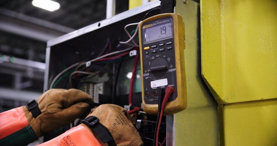
Testing the ground cable’s integrity requires a multimeter․ Set the multimeter to the continuity setting and connect one probe to the negative battery terminal and the other to the chassis ground point where the cable connects․ A reading of near zero ohms indicates a good connection․ Any significant resistance suggests corrosion or a loose connection‚ requiring cleaning or tightening․ A voltage drop test can also reveal excessive resistance under load‚ confirming a faulty ground path․
Body ECU Connection (Driver Side J/B)
The Body ECU (Electronic Control Unit) receives crucial input and sends commands through the driver side junction block (J/B)‚ located behind the left-side dash panel․ This J/B serves as a central distribution point for numerous systems‚ including power windows‚ door locks‚ lighting‚ and the charging system․ Identifying the correct connectors within this J/B is paramount‚ referencing a detailed wiring diagram is essential․
Specifically‚ the Body ECU manages the charging system’s interaction with the combination meter and the battery․ Inspecting the connectors for corrosion‚ loose pins‚ or damage is vital․ A multimeter can verify power and ground connections to the ECU․ Proper communication between the Body ECU and other modules relies on these connections‚ impacting charging functionality and overall vehicle electrical performance․ Careful tracing of wires from the ECU to related components is often necessary․
Charge Indicator Circuit Analysis
The charge indicator light on the instrument cluster relies on a specific circuit‚ originating from the Body ECU and extending through the combination meter․ Analyzing this circuit involves tracing the wiring from the alternator‚ through the Alt-S and AltlAm2 fuses (5A and 30A respectively)‚ to the Body ECU‚ and finally to the charge indicator light itself․ A faulty indicator often points to issues within this pathway‚ not necessarily the alternator․
Using a wiring diagram‚ pinpoint the exact wire colors and connector locations․ Voltage drop tests can identify resistance in the circuit․ Confirm the Body ECU is receiving the correct voltage signal from the alternator․ A malfunctioning combination meter can also cause a false reading․ Thoroughly check all connections within the driver side junction block‚ as this is a common point of failure․ Proper diagnosis requires a systematic approach and accurate wiring information․
Combination Meter Wiring for Charging
The Lexus ES330’s combination meter receives charging system information via dedicated wires connected to the Body ECU․ These wires transmit voltage levels indicating the alternator’s output and battery status‚ illuminating the charge warning light when necessary․ Identifying these specific wires within the meter’s connector is crucial for troubleshooting․ A wiring diagram will reveal the pin numbers and wire colors associated with the charging system․
Testing these wires with a multimeter while the engine is running can confirm proper signal transmission․ A lack of voltage or an incorrect reading suggests a problem either within the combination meter itself‚ the wiring leading to it‚ or the Body ECU․ Inspect the connector for corrosion or loose pins․ Remember‚ the combination meter doesn’t control the charging system‚ but displays its status based on signals received․
Starting System Wiring (2004 ES330)
The engine room junction block and driver side junction block contain the starter circuit’s relay and wiring; diagrams pinpoint connections for diagnosis․
Engine Room J/B – Starter Circuit Details
Within the engine room junction block‚ the starter circuit receives power from the battery‚ routed through a primary fuse before reaching the starter relay control circuit․ The wiring diagram illustrates how the ignition switch signal activates this relay‚ completing the high-current path to the starter motor itself․
Crucially‚ the diagram details the ground connections essential for the starter’s operation‚ ensuring a complete circuit․ Identifying the correct wire colors and terminal locations within the junction block is paramount for accurate troubleshooting․
Pay close attention to the fuse designations – a blown fuse is a common cause of starting issues․ The wiring layout also shows connections to the immobilizer system‚ which can prevent starting if there’s a security system fault․ Understanding these details‚ as depicted in the wiring diagram‚ is vital for effective diagnosis and repair of the starting system․
Driver Side J/B – Starter Relay Location
The driver side junction block‚ concealed behind the left-side dash panel‚ houses the starter relay – a critical component in the starting system․ The wiring diagram clearly pinpoints the relay’s exact location within the block‚ often identified by a specific relay number or designation․ Accessing this relay requires careful removal of the junction block cover and potentially some surrounding trim pieces․
The diagram illustrates the relay’s connections: power input from the battery‚ control signal from the ignition switch‚ and output to the starter solenoid․ Testing the relay’s functionality – checking for proper switching and continuity – is a key diagnostic step․
Ensure the correct relay is being tested‚ as multiple relays may be present․ A faulty relay can prevent the starter from engaging‚ resulting in a no-start condition․ Referencing the wiring diagram ensures accurate identification and testing procedures‚ streamlining the troubleshooting process․

Air Conditioning System Wiring (2004 ES330)
Automatic A/C wiring diagrams reveal connections at the dash reinforcement‚ behind the dash‚ and within the harness near the footwell light․
Automatic A/C Wiring Diagram Overview
The 2004 Lexus ES330’s automatic air conditioning system utilizes a complex network of wiring‚ extending throughout the vehicle’s interior․ Understanding this system requires referencing detailed wiring diagrams‚ often found in PDF format online; Key areas to focus on include the connections at the dash reinforcement on the right side‚ the wiring located directly behind the right side of the dashboard‚ and the intricate wiring within the dash harness‚ specifically near the right-side footwell light․
The blower motor controller receives signals and power through this network‚ regulating fan speed․ The A/C ambient temperature sensor provides crucial input to the system‚ influencing cooling performance․ Tracing these connections back to the driver-side junction block is often necessary for comprehensive troubleshooting․ Diagrams illustrate the flow of power and signals‚ enabling accurate diagnosis of issues like compressor failure‚ blower motor malfunctions‚ or temperature control problems․ Careful study of these diagrams is essential for any repair work involving the automatic A/C system․
Blower Motor Controller Wiring
The blower motor controller in the 2004 Lexus ES330 regulates the speed of the cabin fan‚ responding to inputs from the automatic climate control system․ Wiring diagrams reveal the controller receives power and ground connections‚ alongside signal wires dictating fan speed․ These connections originate from the driver-side junction block and extend through the dash harness‚ ultimately reaching the controller itself‚ often located near the right-side footwell light․
Troubleshooting blower motor issues often begins with verifying power and ground at the controller․ Diagrams pinpoint the specific wire colors and connector pin assignments for these circuits․ Signal wire integrity is also crucial; a damaged signal wire can result in erratic fan operation․ Accessing the controller typically requires removing sections of the dash panel․ Detailed PDF wiring diagrams are invaluable for identifying each wire’s function and ensuring correct reconnection during reassembly‚ preventing further complications․
A/C Ambient Temperature Sensor Wiring
The ambient temperature sensor in the 2004 Lexus ES330 plays a critical role in the automatic climate control system‚ providing the ECU with external temperature data․ This information allows the system to adjust heating and cooling accordingly․ Wiring diagrams illustrate the sensor’s connection to the body ECU‚ typically involving a three-wire configuration: power‚ ground‚ and signal․ The sensor itself is usually positioned behind the front bumper or grille‚ exposed to outside air․
Diagnosing A/C issues often necessitates verifying the sensor’s functionality and wiring integrity․ Diagrams detail the specific wire colors and connector pinouts for easy identification․ A faulty sensor or damaged wiring can lead to inaccurate temperature readings and inefficient climate control․ Accessing the sensor may require removing the front bumper cover․ Utilizing a detailed PDF wiring diagram ensures correct testing and repair procedures‚ preventing further system malfunctions and restoring optimal cabin comfort․
Wiring at Dash Reinforcement (Right Side)
The area behind the dash reinforcement on the right side of the 2004 Lexus ES330 is a complex junction point for numerous wiring harnesses‚ particularly those related to the air conditioning and heating systems․ Detailed wiring diagrams reveal a dense network of connectors and wires servicing components like the blower motor controller and various actuators․ Accessing this area often requires significant disassembly of the dashboard‚ demanding careful attention to avoid damage․
Identifying specific wires within this harness relies heavily on accurate diagrams‚ noting wire colors‚ stripe patterns‚ and connector pin assignments․ Troubleshooting A/C issues frequently involves inspecting connections and testing for continuity in this region․ The PDF wiring diagrams are invaluable for tracing circuits and pinpointing faults․ Proper documentation ensures a systematic approach to repair‚ minimizing downtime and restoring full functionality to the climate control system․
Wiring Behind Right Side of Dash
Behind the right side of the dashboard in a 2004 Lexus ES330‚ a substantial portion of the vehicle’s electrical system is concealed․ This area hosts wiring for the automatic air conditioning system‚ including connections to the A/C ambient temperature sensor and the blower motor controller․ The wiring diagrams emphasize the importance of tracing these circuits carefully‚ as they often branch and interconnect with other systems․
Accessing these wires requires removing dash panels and potentially the glove compartment for sufficient workspace․ The PDF diagrams are essential for identifying each wire’s function and destination․ Correctly interpreting the diagrams allows for efficient troubleshooting of climate control problems‚ such as faulty sensors or blower motor issues․ Careful attention to wire routing and connector security is vital during reassembly to prevent future electrical faults․
Wiring in Dash Harness (Footwell Light Area)
The footwell light area within the 2004 Lexus ES330’s dash harness serves as a central junction point for several wiring circuits․ The wiring diagrams highlight the proximity of the automatic A/C wiring to this location‚ specifically connections related to the blower motor controller․ Accessing this area necessitates careful removal of lower dash panels and potentially the footwell trim pieces to expose the harness․
PDF diagrams are crucial for identifying individual wires within the densely packed harness․ Technicians must pay close attention to wire colors and connector types to avoid misidentification․ Troubleshooting A/C issues often begins here‚ as problems with the blower motor or temperature sensors can manifest in this section of the wiring․ Proper insulation and secure connections are paramount to prevent shorts or intermittent failures․
Accessing Wiring Diagrams (PDF Focus)
Online Lexus ES330 wiring diagrams‚ often in PDF format‚ are essential; these detailed schematics reveal the complex network of wires within the vehicle․
Locating Online Lexus ES330 Wiring Diagrams
Finding comprehensive wiring diagrams for your 2004-2007 Lexus ES330 often begins with a targeted online search․ Several websites specialize in automotive repair information and offer downloadable PDFs‚ sometimes for a fee‚ and others provide access through subscription services․ Specifically searching for “2004 Lexus ES330 wiring diagram PDF” or “2007 Lexus ES330 electrical schematics” will yield relevant results․
Beware of unofficial sources‚ as accuracy can vary․ Reputable automotive forums dedicated to Lexus vehicles can also be valuable resources‚ with members often sharing links to diagrams or even scanned copies of factory service manuals․ Look for diagrams specifically detailing the left kick panel area‚ as this is your focus․ Remember to verify the diagram’s year compatibility to ensure it matches your ES330 model․ Factory service manuals‚ though potentially more expensive‚ offer the most accurate and complete wiring information․
PDF Diagram Navigation and Interpretation
Once you’ve located a PDF wiring diagram‚ understanding its symbols and layout is crucial․ Lexus diagrams typically use standardized symbols to represent components like fuses‚ relays‚ connectors‚ and sensors․ A key or legend within the diagram will define these symbols․ Pay close attention to wire colors and gauge‚ as these are vital for accurate tracing․
When focusing on the left kick panel‚ locate the driver side junction block (J/B) within the diagram․ Diagrams are often organized by system (charging‚ starting‚ A/C)‚ so navigate to the relevant section․ Trace the wires originating from the J/B to identify connections for components like the battery‚ starter relay‚ and charge indicator․ Understand that diagrams may show multiple pages or views; ensure you’re viewing the complete circuit․ Careful interpretation prevents misdiagnosis and ensures safe repairs․